
A Harvard chemistry professor approached me about creating a piece of custom lab equipment. In the course of her research she needs to fluoresce proteins in a controlled way. The light needs to be a known wavelength,365 nanometers UV light, for a controlled amount of time and intensity. It’s also necessary that it’s done on a 96 well plate which is a common standard cell culture tray. They require quite a bright light to make the reaction work so high powered LEDs would be necessary while at the same time it’s also necessary to keep the sample cool. Of course the very bright LEDs should be covered and have safety features to avoid any eye damage. If it gets too hot the reaction won’t work. The procedure the lab had developed used an off-the-shelf UV lamp held over the 96 cell plate with a styrofoam cooler box. This project was completed in 2018.

A 96 Well Plate

The off the shelf UV lamp used by the lab as a temporary solution.
I set out to create a one-off functional piece of lab equipment for the lab. While the concept is feasible, I still felt it prudent to build a small prototype first just to see if it works. There’s a wide range of UV equipment out there for curing glue, party black lights, and various lab applications but nothing we could find fit the bill exactly. Next I searched for UV sources. It was obvious quickly that LEDs would be the most space and energy efficient way to generate light.
The wavelength of light required specialized high-powered LEDs with a emissions spectrum centered around 365nm. I couldn’t find anything retail so contacted suppliers via Alibaba and paid for samples. In a final product The LEDs would be on a PCB, since I was making only one i decided to make it by hand. I used thermal adhesive directly to affix the LEDs directl to the heat sink. To insulate the LED leads from being shorted by the heat sink I cut this electrical tape out. The LEDs leads fortunately could be angled such that no small pieces of wire were required to join them – I could solder them directly to each other. I used the 3D printed frame as jig while soldering.
There was a requirement that all of the cells get exactly the same amount of light, and would need quite a lot based on the current light as a benchmark. To standardize the luminous flux per cell I decided to put an LED under each of the 96 wells. Otherwise a complex system to ensure that all cells get the same amount of light from various LEDs would be required. Because LEDs are current driven, I put the LEDs in series as much as possible to ensure they emit equal amount of light. I was also trying to keep the cost low because as this is academic research funding was not exactly free flowing.
First thing I built was a small 3D printed prototype just for four LEDs powered by an adjustable bench power supply. I procured special 96 well plates designed for UV transparency and designed this LED array to go with it.
The prof. Tested the jig with 4 LEDs at 3 watts each and it proved functional. Compared to the off the shelf version it was showing a similar but slightly less amount of the induced chemical reaction, but otherwise was quite functional. Here’s the output of the test run. More green is better. On the left is the hand held light solution, while on the right is the prototype at three different power settings. This proved it was working but could use a bit more power to be comparable.

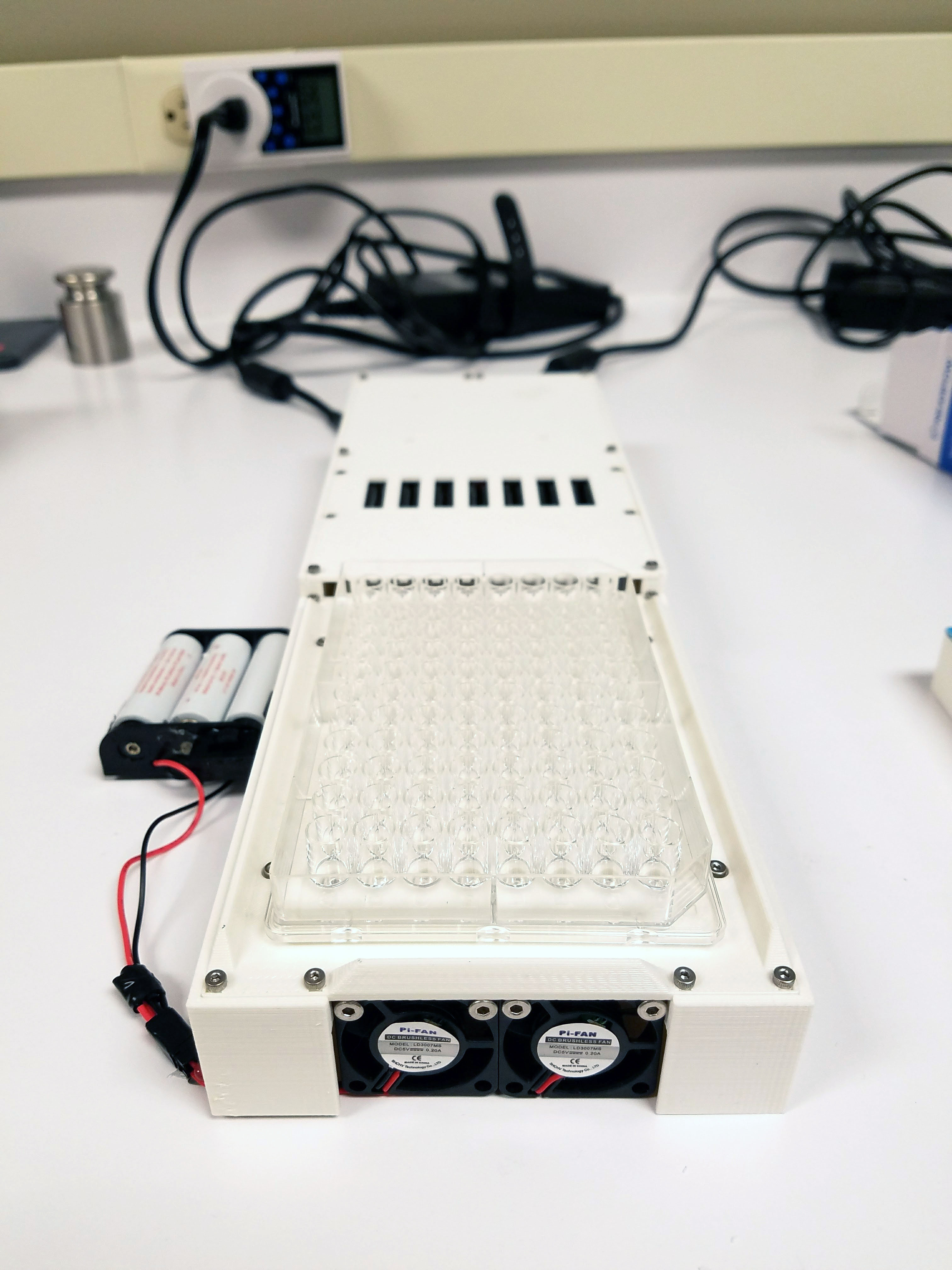
I designed the full-scale version shown here.


It has a large heat sink on the bottom, uses two scrap power supplies from laptops two small fans and 96, 5 watt LEDs. The chassis/enclosure is 3D printed. And the power supply is cut off by safety interlock switches which are only when a cover is placed on the top. I also covered the inside surface of the cover with black tape eliminate UV reflections from the cover. Circuit diagram of 96 plate is here.
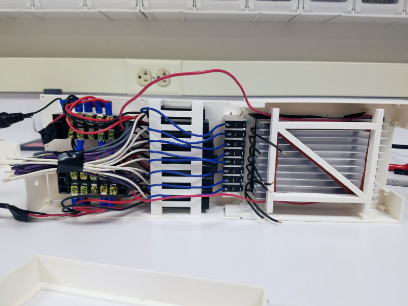
Each long row is in series and each of the long rows are in parallel with each other. Because of the high current draw of these five LEDs, eight separate constant-current LED drivers were used. The current drivers are powered by ac-dc converter borrowed from old laptops. On the end of all of this was a programmable timer switch turn automatically turn off the whole thing. Of course other combinations of parallel/series and LED divers/power supplies could work but this was the lowest cost combination I could find. I did a lot of “shopping engineering” to arrive at these components.
Assembling everything was a small challenge in itself. This is the assembled pieces from below. (I didn’t allot quite enough space for all the wires!)
Here it is all together, functioning.

This version worked on the first try.(!) I was very happy to see that all the lights turned on, the fans worked and the safety switches were all triggered by the cover properly. However one thing was not as good as hoped which was the heat dissipation. Samples were heating up more than was acceptable. I was surprised by this because the prototype was only getting very slightly warm. I decided to order a laptop fan to blow upwards and run this sample in the refrigerated room. Even though usually LEDs are quite cool to the touch these LEDs were extremely powerful (they were very bright despite most emission not being visible light.) Their density created a lot of heat. That’s why I left the whole thing open on the bottom in case it needed more ventilation. The whole experiment normally occurs in a refrigerated room so this would help too.The LED drivers I chose also include a dimming function so in case this was not enough, worst case I would need to adjust the brightness and increase the on-time.
The prototype is now in service in the lab. If this field of chemistry ever booms, I would love to take it it to the next step and consider a production model.
I went into this process not even knowing what and LED driver was, that thermal glue existed and I came out of it with a lesson in how hot LEDs can get. I’m also quite happy to have contributed to science in some small way.
wall e